AIM:
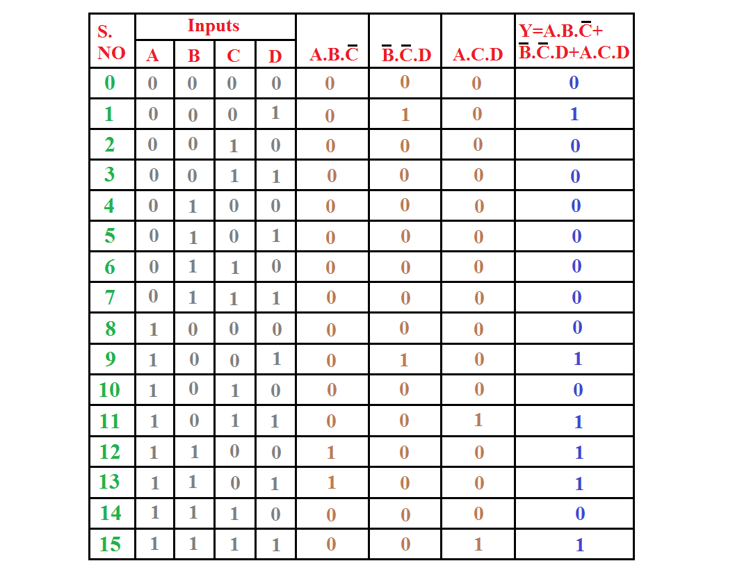
To optimize a 4 variable combinational function SOP(Y=A.B.C' + B'.C'.D + A.C.D), describe it in VHDL code and simulate it.
APPARATUS REQUIRED:
Xilinx V14.7 Software
SUM OF PRODUCT(SOP):
Y=A.B.C' + B'.C'.D + A.C.D
LOGIC DIAGRAMS:
TRUTH TABLE:
FLOW CHART:
PROGRAMS:
library IEEE;
use IEEE.STD_LOGIC_1164.ALL;
use IEEE.STD_LOGIC_ARITH.ALL;
use IEEE.STD_LOGIC_UNSIGNED.ALL;
entity sumofproduct_m is
Port ( a : in STD_LOGIC;
b : in STD_LOGIC;
c : in STD_LOGIC;
d : in STD_LOGIC;
y : out STD_LOGIC);
end sumofproduct_m;
architecture Behavioral of sumofproduct_m is
begin
process (a,b,c,d)
begin
y <= (a and b and (not c)) or ((not b) and (not c)and d) or (a and c and d);
end process;
end Behavioral;
SIMULATION OUTPUT:
PROCEDURE:
Step1: Open xilinx software > go to file > new project > create source file name> select specific folder> next > select proper project settings> we use spartan 3E trainer kit.
Step2: next > finish > go to project > new source > select VHDL module > create file name> next > select input and output > next > finish> write program > if done write programs > click synthesis > right click> run.
Step3: if completed successfully > go to simulation > click source file > right click > new source > select VHDL test bench > create simulation file name > next > select source file > next > finish.
Step4: select simulation file > Isim simulator > click behavioral check syntax > right click > run > if successfully completed. click simulation behavioral > right click > run > wait few seconds > will open new tap.
Step5: click object name > right click > select force clock >
Step6: set all input force clock > if change only period for all inputs >
if use 2input (1st input period 4us and 2nd input period 2us)
if use 3input (1st input period 8us , 2nd input period 4us and 3rd input period 2us)
if use 4input (1st input period 16us , 2nd input period 8us , 3rd input period 4us and 4th input period 2us)
Step7: click Run All > click zoom to full view > check simulation output in this screen
Note: if you want image file > click print screen > open MS paint > cnt +v > save
if you want PDF file > file > print > select doPDF printer > create pdf file name + quality> ok


Truth table practical output bpoda la niga so poda mudiuma plll
ReplyDeleteMantram Nursing Academy is known for providing the NORCET Best Coaching in Hyderabad with expert faculty, updated study materials, and regular mock tests to ensure high success rates.
ReplyDeleteNORCET Best Coaching in Hyderabad